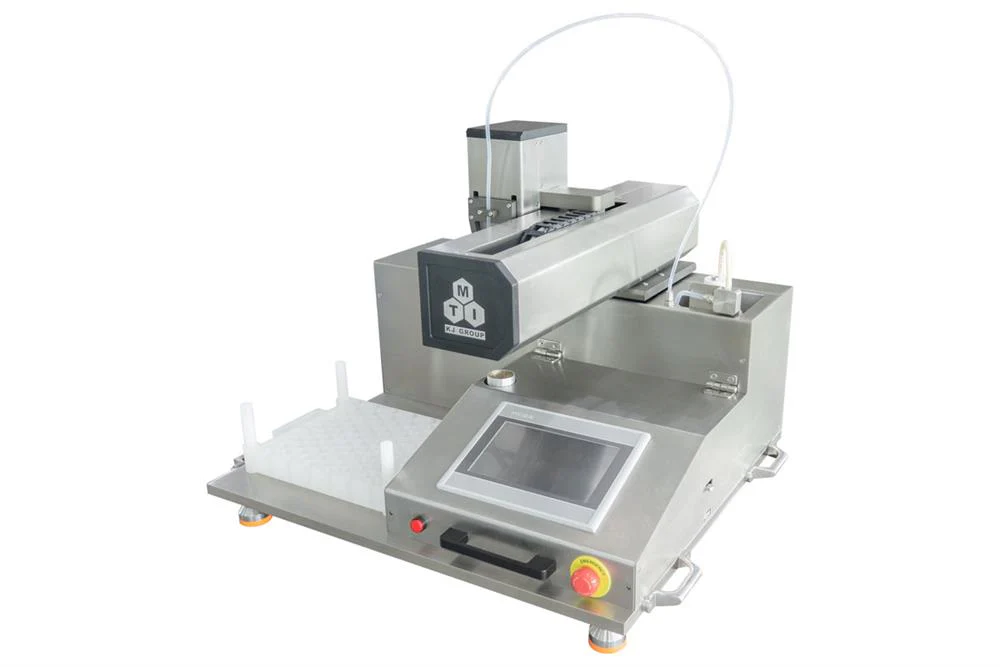
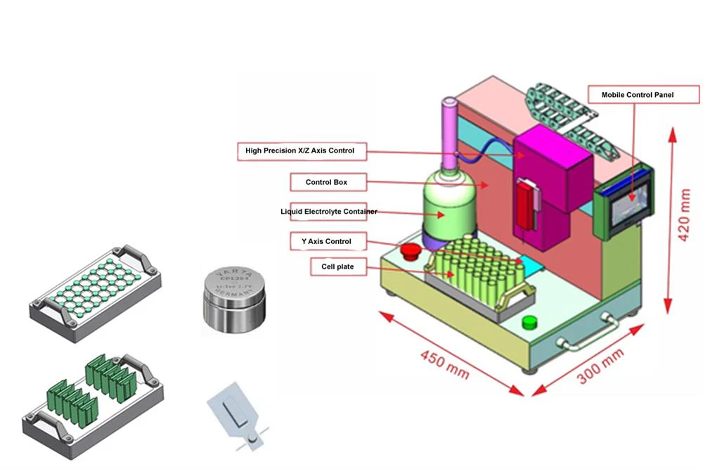
Working diagram for the vacuum electrolyte injection

SPECIFICATIONS:
Input Power
|
- AC 110-220 V±10%, 50/60Hz, Single phase
- Power: 750 W
|
Electrolyte Dispenser
|
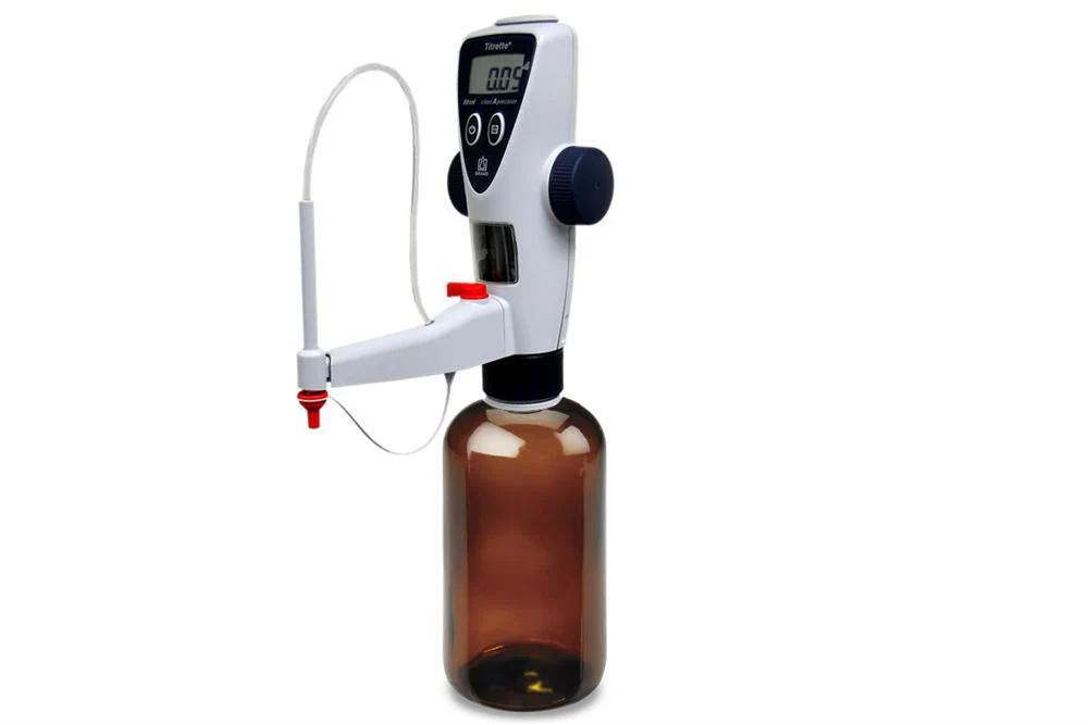
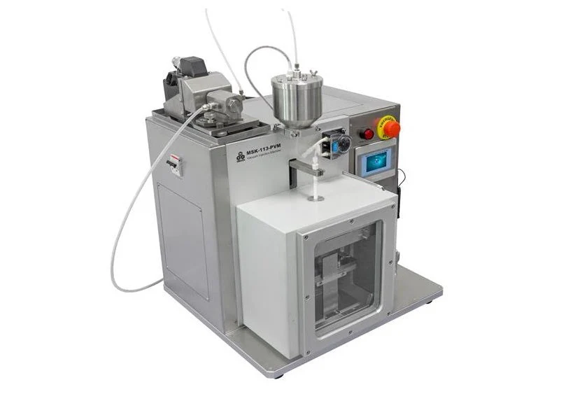
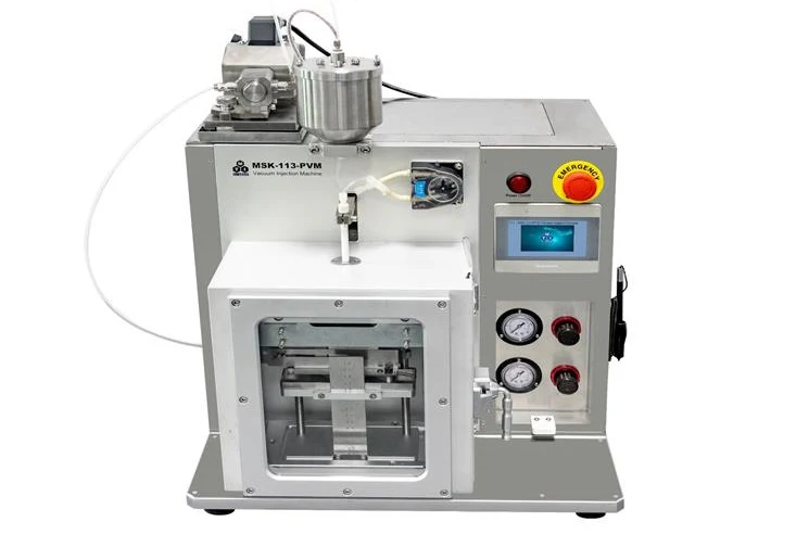
- Precise electrolyte plunger metering pumps are installed for electrolyte filling;
- Electrolyte filling volume and injection rate adjustable via touch screen PLC control
|
Electrolyte Tank
|
|
Cell Size
|
- 4680 cylindrical cells (other size cylindrical cells are also acceptable by providing customized cell holder)
|
Injection Accuracy
|
-
| Electrolyte Volume (g) |
1g |
5g |
10g |
| Injection Accuracy |
±7% |
±3% |
±2.5% |
Injection Pump Speed: 30 r/min, Vacuum: -20 KPa, Standing Vacuum: -60 KPa |
Positive Pressure Filling
|
- Maximum applied pressure 120 KPa, adjustable
|
Vacuum Rate
|
- Maximum - 95 KPa, adjustable
|
Tubing Size
|
- Electrolyte Flow Tubing (PTFE): O.D. 3 mm, I.D. 2 mm
- Injection Tubing (BPT): O.D. 5 mm, I.D. 3 mm
- Transfer Tubing (BPT): O.D. 6.4 mm, I.D. 3.2 mm
|
Vacuum Pump (not included)
|
- Double-stage rotary vacuum pumps are needed for vacuum diffusion, degassing, and vacuum sealing.
- Please click the picture on the left to purchase separately.
|
Working Gas
|
- 0.5~0.8 MPa high purity compressive inert gas (Ar is preferred) is required for driving the pneumatic system in the glove box
- Continues dry inert gas purging for the working chamber is required to maintain a dry atmosphere for electrolyte injection and diffusion
- Air compressors and fitting are required if used in the dry room, but not included. please click here to order
- Attention: If a gas cylinder is used instead of an air compressor(pic2), a two-stage pressure regulator(pic1) must be installed on the gas cylinder to limit the pressure within the required working range for safe operation. Click here to learn the installation of a gas regulator
-
|
Dimension
|
|
Compliance
|
- NRTL Certification is available upon request at an extra cost
|